Cleaning Validation Considerations for Automated Washing Systems

What is cleaning validation and where does it fall in the life cycle validation scheme? How can an automated washing system be validated? This article provides insights that may help answer these questions.
The life cycle approach is a good way to standardize manufacturing and cleaning processes. The 2011 FDA guidance document entitled ‘’Process Validation: General Principles and Practices,’’ which “aligns process validation activities with a product lifecycle concept,” segments process validation into three stages: process design, process qualification, and continued process verification.1
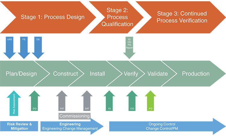
For automated washing systems, Stage 1, process design, comprises the user requirement specifications (URS)—items that should be considered when acquiring the system and the outside parameters that affect its proper use. Stage 2, process qualification, covers the validation strategy, including washer load configuration, cycle operation, acceptance criteria, analytical and sampling methods, and other items. Stage 3, continued process verification, consists of preventive maintenance activities, periodic reviews, and continued monitoring of the cleaning process that can help maintain a state of control when producing drugs at a commercial scale.
Life Cycle Approach
Cleaning is a critical process meant to prevent contamination from active ingredients, excipients (or nonactives), cleaning agent residue, microbial residue, or other contaminants from one process to the next.
The traditional approach to cleaning validation paid little attention to the design of the cleaning parameters. Instead, more emphasis was placed on cleaning validation activities.2 This usually meant at least three cleaning trials and testing of extreme conditions (such as the lowest possible detergent concentration), wash and rinse cycle temperatures, and times for the various steps of the cleaning process. When this approach is applied to validation, the analyst often observes some out-of-specification (OOS) results that may require additional testing and justifications. Once the test runs are acceptable and the report written and approved, however, the company then considers the automated washer and cleaning cycle validated. Change or optimization is a huge hurdle.
In contrast, the life cycle approach places more emphasis on understanding the cleaning process, equipment design, and continued monitoring of the operation to ensure quality results. This approach, presented in the abovementioned FDA guidance, incorporates recommendations from International Conference on Harmonisation (ICH)* guidance documents covering pharmaceutical development and quality by design (Q8), quality risk management (Q9), and pharmaceutical quality systems (Q10).3 ,4 ,5
The life cycle approach guiding principles are:
- Quality must be built into the process
- Quality is not guaranteed by in-process or final process testing
- To ensure consistent quality, manufacturing processes must be defined, and continued monitoring applied
Because the life cycle approach can be applied to cleaning validation of automated washer systems, this article covers equipment design requirements of the automated washer cycle all the way through continued verification of the equipment and cleaning cycle.
Three stages
The life cycle approach is divided into three stages:1
Stage 1: process design—The commercial manufacturing process is defined, based on knowledge gained through development and scale-up activities. This ensures that variables within the process are identified and critical variable limits are defined.
Stage 2: process qualification—The process design is evaluated to determine if it is capable of reproducible commercial manufacturing. This verifies that the process, as designed, produces the expected results.
Stage 3: continued process verification—Critical variables are monitored to ensure that the process remains in a state of control during routine production.
The life cycle approach emphasizes the design and monitoring stages of the process. This includes understanding critical cleaning parameters (CCPs) and noncritical cleaning parameters, and defining critical quality attributes (CQAs) for cleaning. Increased emphasis on continued monitoring ensures that the process is running in a state of control. Process analytical technology, which relies on continuous monitoring to record and process data in a timely manner, can also be used to satisfy Stage 3 continued process verification requirements.6
The flow chart shown in Figure 1 depicts the life cycle approach as it relates to traditional markers in sourcing an automated washer and using it for cleaning parts within a validated cleaning process. The initial focus in Stage 1 is on various specifications, key process attributes, and acceptance criteria, while using a risk-based
* Full title: International Conference on Harmonisation of Technical Requirements for Registration of Pharmaceuticals for Human Use
Figure 1: Life cycle approach7
- 1 a b US Food and Drug Administration. Guidance for Industry. “Process Validation: General Principles and Practices.” January 2011. http://www.fda.gov/downloads/Drugs/.../Guidances/UCM070336.pdf
- 2Lopolito, P., and E. Rivera. “Cleaning Validation: Process Life Cycle Approach.” In Contamination Control in Healthcare Product Manufacturing, Vol. 3, edited by R. Madsen and J. Moldenhauer. PDA and DHI Publishing, 2014.
- 3US Food and Drug Administration. Guidance for Industry. “Q8 Pharmaceutical Development.” May 2006. http://www.fda.gov/OHRMS/DOCKETS/98fr/05d-0021-gdl0002.pdf
- 4———. Guidance for Industry. “Q9 Quality Risk Management.” June 2006. http://www.fda.gov/downloads/Drugs/.../Guidances/ucm073511.pdf
- 5———. Guidance for Industry. “Q10 Quality Systems Approach to Pharmaceutical cGMPRegulations.” September 2006.http://www.fda.gov/downloads/Drugs/.../Guidances/UCM070337.pdf
- 6———. Guidance for Industry. “PAT – A Framework for Innovative Pharmaceutical Development, Manufacturing, and Quality Assurance.” September (2004). http://www.fda.gov/downloads/Drugs/Guidances/ucm070305.pdf
- 7Hofacre, M. “Technical Report No. 48. Moist Heat Sterilizer Systems: Design, Commissioning, Operation, Qualification, and Maintenance.” Presentation, 2010. https://www.pda.org/docs/default-source/website-document-library/chapters/presentations/new-england/pdatechnical-report-48-moist-heat-sterilizer-systems.pdf?sfvrsn=6
Stage 1: Process Design
This stage requires a validation strategy. A cleaning validation master plan should already be in place and include items such as cycle development, selection of cleaning agents, analytical and sampling methods, calculating acceptance criteria, handling and storage procedures for cleaned components, and cleaning equipment validation.
If this is a new equipment installation—often the case with automated washer cleaning validation—then the equipment URS, functional specifications (FS), and design specifications (DS) are also important. This information will be critical to successful commissioning and validation.
Validation strategy
The validation strategy for automated washers should start by collecting information on the parts to be cleaned, including materials of construction, type of product contact soil, and condition of the soil on the surface. This information, shown in Table A, is critical for a risk-based approach in developing a grouping strategy, designing the cleaning cycle, and defining the parts loading configuration.
To develop loading configurations, the best option is a custom-designed rack that provides a specific place for each item. A second would be to have a range of sizes for items that can be placed at specific locations, such as a 200-, 400-, 600-, 800-, or 1000-milliliter beaker that can be placed on a single spindle for cleaning. Yet another option would be to use baskets in which the description, quantity, and orientation of the items would be defined per basket, and the location or placement of the basket would be defined on a parts washer rack. During this design stage, it’s important to group or bracket items by comparing largest and smallest sizes, for example, to test worst-case load configurations.
A single process soil may be cleaned, as would be the case with filling equipment, or several soils can be washed in a single cycle. In either case, the cleaning cycle must remove residues to acceptable health-based limits. Both the sampling technique and analytical methodology should demonstrate that these limits are met.
Cleaning is a critical process meant to prevent contamination.
Cleaning cycle development
The goal of cycle development is to adjust the critical cleaning parameters to meet acceptance criteria using the shortest and most energy-efficient cleaning cycle.
Cycles in a parts washer generally consist of: 8
- Prewash
- Wash
- Rinse
- Final rinse
- Drying
- Additional wash and rinse steps (optional)
- Additional steps such as sanitization or lubrication (depending on the parts to be cleaned)
Cycle development may be performed at the manufacturing site or during the commissioning steps after installation. Waiting too long could create major schedule delays and difficulty modifying equipment after fabrication.
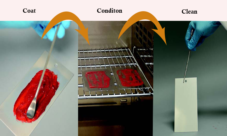
The best time for cycle development is during the preparation of the parts washer URS, using laboratory (coupon) studies, as shown in Figure 2. For these studies the process residue is coated on a coupon of material similar to the parts, conditioned as it would be during processing, and then cleaned in a manner similar to the parts washer.
Laboratory testing is a great tool for defining cleaning cycle CCPs such as cleaning agent, concentration, temperature, wash time, water quality, water prewash temperature, and dirty hold time.9 The goal should be to define the normal operating parameters (often called the area of control) to meet cleanliness criteria, define the area of success, and develop your area of knowledge. What condition, for example, would result in a failure? This understanding of the design space is outlined in ICH Q83 and should be part of the cleaning cycle development work.
To assist in cycle development, process and cleaner evaluation services are also available pre- and post-installation through cleaning agent suppliers. This type of laboratory testing can also help define a worst-case soil that can be used during validation activities, which can save time during the validation stage.10 ,11 ,12
Figure 2: Coupon studies
- 8Van Houtte, O., P. Lopolito, and M. Dion. “Automated Washing Principles and Common Mistakes.” Pharmaceutical Engineering 35, no. 5 (October 2015).
- 9Verghese, G. “Selection of Cleaning Agents and Parameters for cGMP Processes.” Proceedings of the INTERPHEX Conference, Philadelphia. Reed Exhibition Co, Norwalk, CT,1998.
- 10Rathore, N., W. Qi, C. Chen, and W. Ji. “Bench-Scale Characterization of Cleaning Process Design Space for Biopharmaceuticals.” Biopharm International 22, no. 3 (March 2009):32–44.
- 11Sharnez, R. “Leveraging Small-Scale Models to Streamline Validation.” Journal of ValidationTechnology 14, no. 4 (2008): 19–22.
- 12Hadziselimovic, D., and P. Lopolito, P. “Critical Cleaning of Carbomer Containing Products.” Journal of GXP Compliance 16, no. 3 (Summer 2012): 32–38. http://www.ivtnetwork.com/sites/default/files/IVTGXP0712_032-038_Lopolito%20PeerTitle-%7B1416310%7D.pdf
Analytical and sampling methods
As defined by the US Code of Federal Regulations, Title 21, Part 211, Subpart I, Section 211.165, “The accuracy, sensitivity, specificity, and reproducibility of test methods employed by the firm shall be established and documented.” 13
ICH Q2B guidance—a harmonized approach to the requirements for analytical method validation—provides additional information.14 ICH Q2B guidance was not developed specifically for analytical methods used in cleaning validation; the required elements of linearity, precision, range, robustness, accuracy, ruggedness, specificity, limit of quantitation, and limit of detection, however, are commonly applied to analytical method validations for cleaning validation (Table B).2
Analytical methods can fall into two categories:
Specific methods (preferred) identify the number of targeted species found in the presence of expected interferences. These methods can be ultra-performance liquid chromatography, ion chromatography, and atomic absorption.
Nonspecific methods, which can be total organic carbon (TOC), conductivity, and titration, take into account residue from all contributing factors. Visual inspection should be included for each item removed from the parts washer, and the procedure should classify a course of action for observed scratches, etching, dents, dings, and the like. These items may not be cleaning-related visual failures, but could be due to handling or wear.
The most common sampling methods are surface swabbing and rinse sampling. A less common procedure is direct surface sampling with an instrument such as a handheld Fourier transfer infrared spectroscopy or near-infrared spectroscopy.
For swab sampling, most companies use a single-swab method. In this approach, the surface is first sampled in overlapping strokes, then the swab is flipped over and used in overlapping strokes at a 90-degree angle to the first set (Figure 3). In the two-swab method, an area is sampled with a wet swab as noted above, then sampled by a second dry swab utilizing the same method. In both methods, water or another diluent is added to a vial with the swab or swabs. The analyte is extracted (or desorbed) from the swabs for analysis. Swab templates can be used for training, but not for actual part sampling, due to possible cross-contamination from the template to the swab.
In rinse sampling, small bottles, beakers, and other items are placed in a sterile plastic stomacher bag. Rinse water is added, the bag is sealed, and the contents mixed by shaking. A final rinse water sample or in-line measurement for conductivity and possibly TOC is used; the items must also be visually clean.
Whether using swab or rinse sampling methods, it is important to establish residue-recovery studies. The final rinse water specification and visually clean criteria should be confirmed with some level of surface sampling through swab, rinse, or direct methods.
Acceptance criteria
The cleaning validation master plan should help determine which residue to test for, and justify the limits established for surfaces or final rinse water samples. It is common to use purified water specifications for pH, conductivity, TOC, and microbial limits, along with a carryover estimate calculation based on residue toxicity. Residue limits are commonly calculated for drug active, cleaning agent, and bioburden, but may also include endotoxins, degradation products, excipients, or even the presence of color and fragrances. It’s helpful to include photographs or diagrams of the items to sample, and provide a rationale for selecting them. Such examples may be difficult-to-clean parts or those with the most complicated design.
In addition to setting limits on residue, it is often common to set acceptance criteria for the level of residual water left behind after the drying step. No droplets or residual water should remain on or in the items because this can lead to microbial growth.
If the cycle includes a sanitization/disinfection step, thermal strips or biological indicators can be used during the design phase to establish a log reduction. Chemicals, such as blends of hydrogen peroxide and peracetic acid (such as SporKlenz RTU disinfectant at a 1:50 dilution for 5 minutes), or hot water are effective sanitizers. Common time and temperature used for hot water pasteurization is 30 minutes at 63°C, 15 seconds for 72°C, and one second for 83°C.15
-
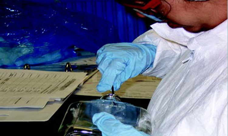
Figure 3: Swabbing method -
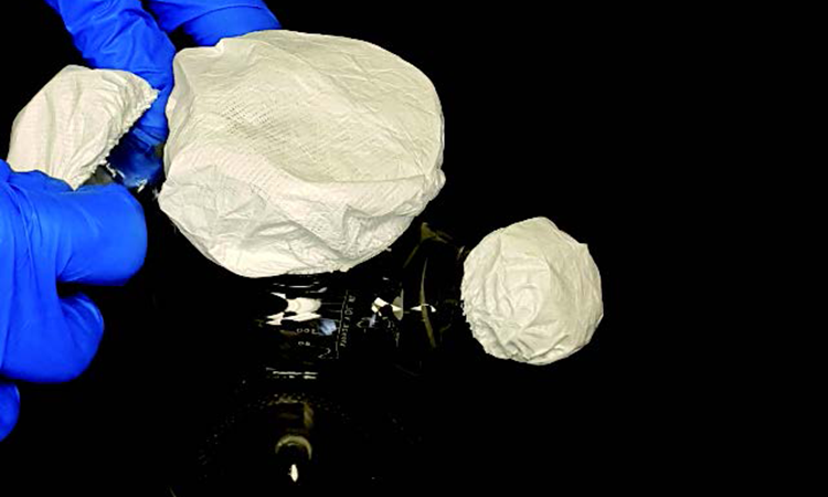
Figure 4: Semipermeable cover -
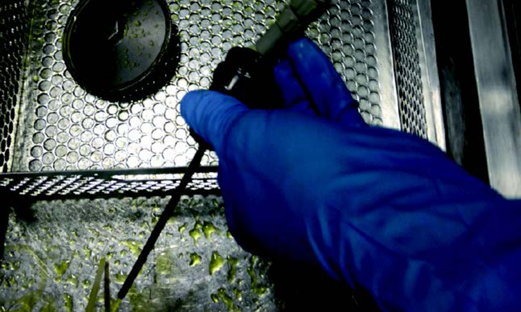
Figure 5: Riboflavin coverage testing
- 13US Code of Federal Regulations. Title 21, Part 211, Subpart I, Section 211.165: “Testing and Release for Distribution.” http://www.accessdata.fda.gov/scripts/cdrh/cfdocs/cfcfr/CFRSearch.cfm?fr=211.165
- 14US Food and Drug Administration. Guidance for Industry. “Q2B Validation of Analytical Procedures: Methodology.” November 1996. http://www.fda.gov/downloads/drugs/guidancecomplianceregulatoryinformation/guidances/ucm073384.pdf
- 2
- 15Wardrip, C. L., J. E. Artwohl, and B. T. Bennett. “A Review of the Role of Temperature Versus Time in an Effective Cage Sanitization Program.” Contemporary Topics in Laboratory Animal Science 33, no. 5 (1994): 66-68 1994.
The life cycle approach emphasizes the design and monitoring stages of the process.
Handling and storage procedures
Activities in Stage 1 should also define handling and storage procedures for cleaned items. These should be removed dry and covered during storage to prevent surface particle collection and microbial contamination. Semipermeable wraps or covers are an excellent way to protect clean items (Figure 4).
An acceptable storage time or clean hold time is generally based on handling and storage practices using visual inspection, with bioburden monitoring after a defined storage time. (Bioburden testing is also performed on dirty items to establish the bioburden load and types of microbes commonly seen.) Some companies skip the bioburden testing after the cleaning/sanitization cycle but keep the bioburden testing after the clean hold storage time to confirm the bioburden reduction of the cleaning cycle, and to verify that the handling and storage is sufficient.
User requirement specifications
In situations where an automated washing system is used, the URS plays a major role in the validation process. This information allows suppliers to provide equipment that will be optimized for the specific application. Incorrect or incomplete URS are likely to cause problems down the line, so it is very important to get them right from the start. A URS document details all information the supplier needs to provide the best equipment for the stated purpose. Description of the application, items to be cleaned, washer chamber size, project schedule, and timeline are some URS fundamentals. Table C lists most common items found in a URS document for an automated cleaning system.
Factory acceptance test
After the washer has been manufactured according to the URS, it is a good practice to execute a factory acceptance test (FAT). This highly recommended practice may help minimize overall qualification time, since some portions can potentially be reused for on-site qualification. Once the unit is installed, some tests may not need to be executed again (depending on risk assessment).
The FAT should allow enough time to review the design, manufacturing, and qualification documentation, and verify that all desired features, options, and accessories are present and meet the user’s expectations. Typically, all alarms, inputs, and outputs are tested. In most cases, operational tests are also conducted to ensure compliance with functional specifications. In addition, the user may perform a simultaneous audit of the supplier’s quality system.
Coverage testing, another important portion of the FAT, should be performed with the parts that will be used on-site. Coverage is often considered the most critical cleaning parameter, since a lack of coverage means that the cleaning solution does not reach all internal or external load items surfaces. Coverage testing is even more important when difficult-to-clean items such as tubing, hoses, or complicated parts are processed. Capturing potential coverage issues during the FAT will prevent the risk of rework and delays at the user’s site.
In a typical coverage test, the inside surface of load items are sprayed with riboflavin, then positioned on loading racks according to the predefined specifications.17 The washer chamber, loading racks, and load items are then also sprayed with riboflavin (Figure 5), and the solution is allowed to dry for a few hours at ambient temperature.
A short rinse-only cycle should then be run. Once the rinse cycle is completed, the load items should be removed quickly from the wash chamber and inspected in a dark area using an ultraviolet light. Since riboflavin is water-soluble, this will identify areas where it is still present, which indicates that water did not reach that area. (Many equipment suppliers also offer to perform actual cleaning tests with user-provided parts, soils, and cleaning agents.)
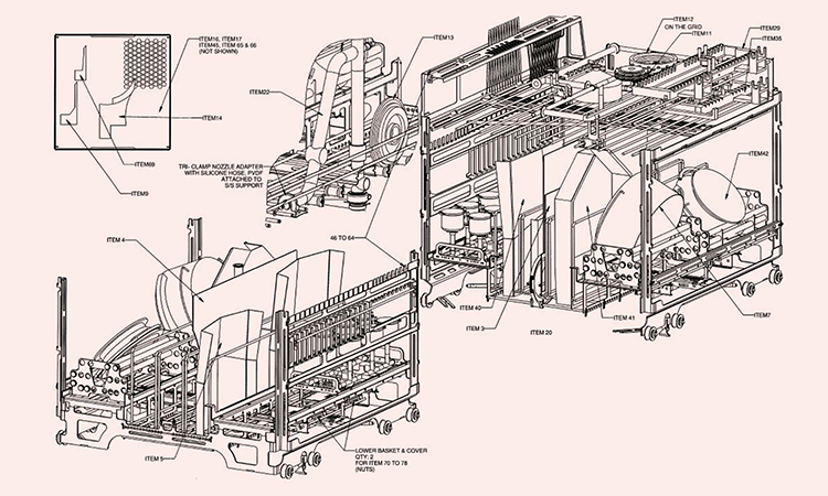
To ensure consistent cleaning results are achieved, the washing system manufacturer can develop a loading specification document (Figure 6) that shows the respective locations of the parts on the loading accessories. It is critical that operators replicate this pattern when loading the washer with actual dirty parts, because a surface that is not in contact with water (and cleaning solution) will never be clean.
Figure 6: Example of a customized loading rack
- 17Verghese, G., and P. Lopolito. “Cleaning Engineering and Equipment Design.” In Cleaning and Cleaning Validation, Vol. 1, edited by Paul Pluta. Davis Healthcare International and Parenteral Drug Association, 2009. https://store.pda.org/TableOfContents/CleaningValidationV1_TOC.pdf
STAGE 2: PROCESS QUALIFICATION
Stage 2, qualification of the automated parts washer and cleaning validation could be approached as a readiness check. Before starting the process, the following should be confirmed:
- Cleaning documentation including protocols and operating procedures have been approved
- Personnel have been trained on the documentation and procedures
- Utility supply systems have been qualified
- Analytical methods and sampling procedures have been validated
- Suppliers of cleaning agents have been approved
- Automated washer equipment is fully functional
Qualification
Stage 2 typically includes installation qualification (IQ) and operation qualification (OQ) to determine that the automated washer:
- Has been installed as specified and the utilities are sufficient to maintain operation
- Is operating as specified
These procedures may include a repeat of the riboflavin coverage testing, a successful run of a complete cleaning wash cycle, verification that all alarms are functioning properly, and confirmation that sensors/probes are calibrated and functioning as designed.
The next step is to execute the performance qualification (PQ) of the washer. Sampling should be performed on the soiled parts to establish a baseline, and on the cleaned items to demonstrate that the final rinse water acceptance criteria corresponds to the cleanliness of the parts washed.
Cleaning validation
As noted above, the traditional cleaning validation (PQ) approach of evaluating three runs may not be applicable. Instead, the number of runs may depend on the testing performed during the Stage 1 design and risk assessment. Evaluating worst-case critical parameters is also not applicable because critical parameters identified during the design stage were identified and monitored or controlled. The goal of the PQ is to demonstrate that the normal operating cleaning cycle using the automated parts washer successfully removes the residue(s) of interest to predetermined acceptable limits.
The PQ process should be thoroughly documented and approved. Any deviations, changes, or OOS events should be recorded and a risk assessment performed to assess impact to the PQ activities.
| Description | Quantity | Height, mm | Outer diameter (OD) |
Weight, kg | Critical information |
Drawing or picture number |
Notes |
|---|---|---|---|---|---|---|---|
| Filling needle | 8 | 110 | 15 | NA | Process soil: low concentration protein |
 |
Photo 28 |
| Filling pump | 8 | 174,5 for pump 150 for plunger |
Pump OD 70,6 Plunger inner dia. 18 |
NA | Process soil: Low concentration protein, material: external is 316L SS, pump internal is porcelaine, can separate wash |
 |
Photo 29 |
| Glass bottle | 1 | 300 | 180 | NA | Process soil: low concentration protein |
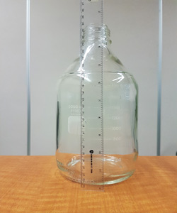 |
Photo 30 |
| Characteristic | Recommended criteria |
|---|---|
| Precision | Precision should be assessed using at least nine determinations (3 concentrations with 3 replicates each) covering the specified range and reported as Relative Standard Deviation (RSD). |
| Limit of quantitation (LOQ) | The LOQ can be estimated by measuring the baseline noise multiplied by 10. This value must be less than the cleaning validation acceptance limit. |
| Limit of detection (LOD) | The LOD can be estimated by measuring the baseline noise multiplied by 3. This value must be less than the cleaning validation acceptance limit. |
| Accuracy | Accuracy should be assessed using at least nine determinations (3 concentrations with 3 replicates each) covering the specified range and reported as percent recovery. The percent recovery should be close to 100%. |
| Specificity | Specificity may be demonstrated by comparing the test results of samples containing analyte plus other expected components versus samples of analyte only. |
| Linearity | Linearity should be established with a minimum of five concentrations and three replicates each. The coefficient of determination (R2) of the linear regression should be not less than 0.99. |
| Project scope | Available utilities | Washer location environment | |
|---|---|---|---|
|
|
|
|
| Loading accessories (racks) | |||
|
|||
| Standards and guidelines | |||
|
|||
| Design requirements | Documentation requirements | ||
| Electrical Instrumentation (preferred vendors, accuracy) Tagging for instrumentation Labeling |
Paper or Electronic Language |
||
Mechanical
|
Design documentation
|
||
Control system
|
Manufacturing documentation
|
||
Process monitoring
|
Process records
|
Manuals
|
Qualification
|
Stage 3: Continued Process Verification
The main purpose of the third life cycle stage is to provide continued assurance that the cleaning procedure is performing as expected, and that it remains in a state of control for the life of the product(s) being manufactured. In this stage, the facility is manufacturing product and the cleaning procedure and automated washer are operating within the normal range.
Stage 3 typically includes regular reviews of the cleaning performance, cleaning procedures, training program, change controls, deviations, corrective and preventive actions, and preventive maintenance activities.
Preventive maintenance
The initial preventive maintenance program of the automated washer and parts should be based on the manufacturer’s recommendations, and adjusted as the equipment ages or real-time performance metrics support indicate. Laboratory testing can also be used to investigate items such as compatibility between gasket and tubing materials.
| Changes to | May affect |
|---|---|
| Detergent | Cleanability of the soils |
| Cleaning parameters | Cleanability of the soils |
| Analytical method | Surface coverage, equipment drainability, change over time |
| Personnel | Training and level of experience |
| Dirty hold time | Cleanability of soils, level of bioburden |
| Cleaning hold time | Extraneous matter, bioburden |
Stage 3 includes trend analyses of the measured CPPs and CQAs (e.g., online conductivity and TOC of the final rinse water) as well as drying temperature/time and ramp rates, which can increase cycle times.18 ,19 Data trending helps supports corrective actions prior to deviations or OOS results, which can compromise the quality of products manufactured.
The life cycle approach, which emphasizes understanding and effective continuous verification of the cleaning process, should be open to change control to improve its efficiency and drive down production costs while maintaining high quality standards. Table D lists changes to the cleaning process and possible results of the of the change.2
Conclusion
The cleaning life cycle approach (design, qualification, and continued verification) focuses on design and monitoring of the cleaning process as well as a better understanding of the design process (critical parameters and URS of the automated parts washer). This promotes continuous improvements and real-time science-based responses to OOS results and change management. Industry tools are the backbone to the life cycle approach and these elements can be incorporated into cleaning validation when using automated parts washers.
Whether using swab or rinse sampling methods, it is important to establish residue-recovery studies.
- 18Dion, M., O. Van Houtte, and G. Verghese. “On-Line TOC Monitoring in GMP Parts Washers.” Pharmaceutical Engineering 34, no. 2 (March/April 2014): 80–87.
- 19Bader, K., J. Hyde, P. Watler, and A. Lane. “On-Line Total Organic Carbon (TOC) as a Process Analytical Technology for Cleaning Validation Risk Management.” Pharmaceutical Engineering 29, no. 1 (January/February 2008): 8–20.
- 2


