Risk Assessment for Thermal Influences on Filter & Container Closure Integrity Testing

Patient safety depends on the reliability of sterility-assurance tests. Sterilizing grade filter integrity testing (FIT)—diffusion and bubble point tests—and container-closure integrity testing (CCIT) of single-use bags (pressure-decay test) are therefore critical.
In the pharma-biotech industry, it is generally understood that environmental temperature drifts can influence FIT and CCIT test values. Using the ideal gas law as a rule of thumb, homogeneous temperature changes of 1°C inside the sample during the diffusion measurement phase can affect the diffusion test result by about 25% (see results). Environmental temperature drifts can generate both false passed test results—which can put patients’ lives in danger—and false failed test results, which may quarantine otherwise acceptable product and contribute to drug shortages. This is why stable temperature is a prerequisite for the abovementioned tests. Temperature changes do happen, nevertheless, due to factors such as laminar airflow and nearby steam-sterilizing autoclaves or freeze dryers. And post-use testing in a low-grade environment could also be subject to temperature variations. Wetting conditions are another concern, as liquid that is too cold or too warm will thermally equalize with the environment during the measurement phase. (Wetting liquid temperature will not be discussed extensively in this article.)
Definitions and abbreviations
CCIT: Container closure integrity testing; used for single-use bags and other means of containing medicinal and other products
False failed test result: A failing integrity test result for an integral sample
False passed test result: A conforming integrity test result for a defective sample
False negative: A term used in sterility testing for a test giving a sterile result although the sample is unsterile. This term must not be used for integrity testing results as confusion about the meaning may occur.
False positive: A term used in sterility testing for a test giving an unsterile result although the sample is sterile. This term must not be used for integrity testing results as confusion about the meaning may occur.
FIT: Filter integrity testing; used for sterilizing grade filters, typically with a pore size of 0.2 or 0.22 μm
Sample: Generic term for a filter capsule, a filter in a filter housing, single-use bag, or a vessel
The effect of temperature change is complex, and cannot be explained by the ideal gas law alone. The influence on test results also depends on whether the sample is made of stainless steel (multiuse filter housing) or plastic, such as a polypropylene (PP) filter capsule or single-use bag in ethylene vinyl acetate, since different materials react differently to temperature changes depending on their thermal expansion factors and heat conductivity. Different test methods also yield different test results. The diffusion (also called forward-flow) and pressure-drop tests are, for instance, more affected by temperature variations than is the bubble point test (see results).
This article shows experimental data on the thermal behavior of filter capsules in PP compared to multiuse filter housings in stainless steel when exposed to temperature changes during a diffusion test. The temperature changes generated during these trials were much greater than would be expected under normal conditions. Samples would not be put into water under normal conditions, either. This was necessary, though, to generate diffusion curves that clearly demonstrate the complexity of this behavior.
The purpose of this article is to increase understanding of thermal impact on FIT and CCIT, and to provide a tool for improved risk assessment, such as failure mode effects analysis (FMEA).
Materials
- Compressed air
- Hot and cold water
- A 10-liter bucket
- Axial fan heater (AEG, HS 204 ST 2000W)
- Reference temperature sensor (Sika Electronic TT31048)
- Filter-integrity tester
- Test tubing
- 10-inch stainless steel housing
- 10-inch filter cartridge (0.2 micrometers [μm])
- 10-inch filter capsule in PP (0.2 μm)
- 5-inch filter capsule in PP (Sartopore2 0.2 μm)
Remarks
The filter-integrity test device used for these trials measures diffusion according to the pressure-decay method, combined with a sample net volume determination (see DIN 58356 part 2). Other devices may use volume dosing. Regardless of measuring method, all flow-measuring devices are bound to the physics of the ideal gas law (pV = nRT). In addition, the behavior of the test sample when it is exposed to thermal variations is independent from the testing device.
Differences in behavior between devices based on software and safety parameters for detecting unstable conditions are still possible, however. This article does not intend to make any comparison between devices. The risk assessment suggested in this article should therefore take into account the device being used.
TRIALS
Test 1
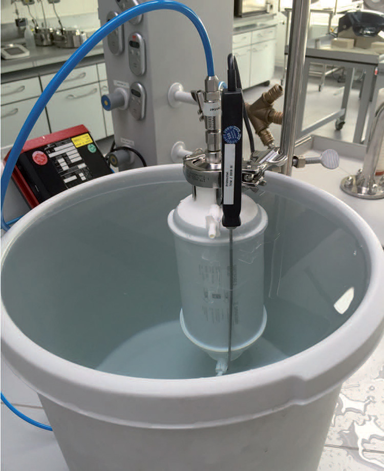
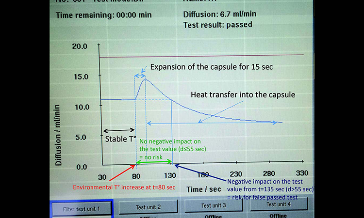
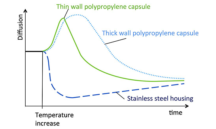
A diffusion test under stable environmental conditions at an ambient room temperature of 22°C was performed on a 10-inch filter capsule. After 80 seconds of measurement the filter capsule was entirely submerged in a bucket with water at 30°C to generate a quick temperature increase (Figure 1). The diffusion curve showed can be seen in Figure 2.
Interpretation
During the first 80 seconds the temperature is stable. This generates a stable pressure drop per time unit, which is displayed as a stable diffusion rate. When the PP capsule is placed in warm water, the capsule volume expands and its volume increases. This generates an approximately 15-second pressure drop per time (Δp/t) increase, which is interpreted as an increased diffusion rate by the integrity tester.
As PP does not conduct heat efficiently, heat transfer into the test gas is slow. When the heat transfer takes place, the pressure drop per time is reduced. The integrity tester interprets this as a reduction of the diffusion rate.
Between t = 80 seconds and t = 135 seconds, the diffusion value is above or equal to its initial value. During this lapse of 55 seconds there is no negative impact on the test value, meaning there is no risk for a false passed test result. After 55 seconds of heating, the test value is back to its initial value. Beyond t = 135 seconds (beyond 55 seconds of heating) the test value goes below its initial value, thus generating a risk for a false passed test result that could put patients at risk.
“Environmental temperature drifts can influence FIT and CCIT test values”
Test 2
The same trial performed under identical thermal conditions on a filter cartridge inside a stainless steel housing resulted in a test abortion as soon as the filter housing was put into the bucket of warm water. This was due to a hard-coded algorithm used by the integrity tester to detect unstable environmental conditions; no graph could be displayed.
Interpretation
Table A shows that the thermal expansion of stainless steel is significantly smaller than that for PP. (The thermal expansion of a given material is typically inversely proportional to its melting temperature.) In combination with stainless steel’s more efficient heat transfer, this generates a quick pressure increase inside the housing when it enters the warm water that exceeds the diffusive pressure drop. In fact, if the integrity tester used for these trials detects a pressure increase of 2 millibars (mbar)/10 seconds or more, the test is aborted with an error message.
Test 3
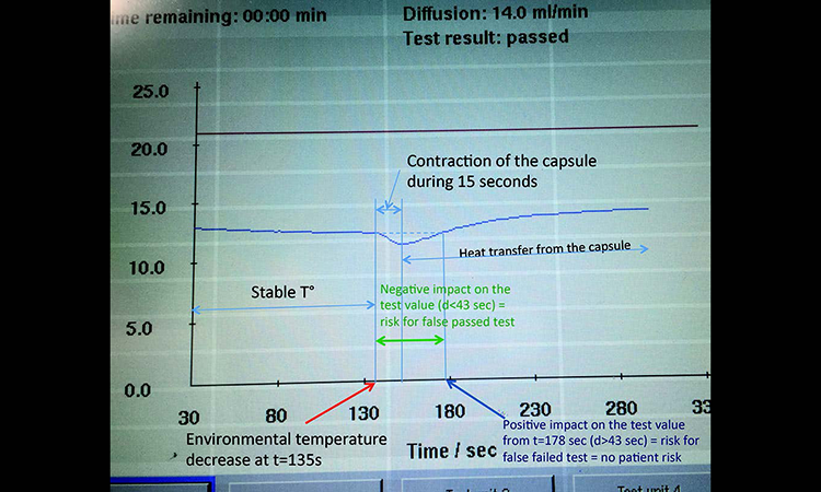
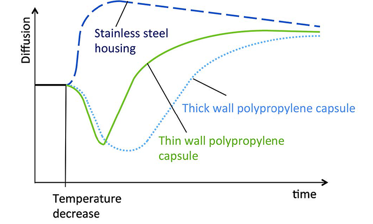
A diffusion test under stable environmental conditions at an ambient temperature of 22°C was performed on a 10-inch filter capsule. After 135 seconds of measurement the filter capsule was entirely submerged into a bucket of water at 17°C to generate a quick temperature decrease. The diffusion curve is shown in Figure 3.
Interpretation
When the PP capsule enters the cold water the capsule contracts and its volume is reduced. This slows down the pressure drop per time over approximately 15 seconds, which is interpreted as a reduction in the diffusion rate by the integrity tester.
As PP does not conduct heat efficiently, heat transfer from the test gas to the water is slow. When the heat transfer takes place, pressure drop per time is increased. The integrity tester interprets this as a diffusion rate increase.
Between t = 135 seconds and t < 178 seconds, the diffusion value is below its initial value. During this lapse of 43 seconds there is a negative effect on the test value, raising the possibility of a false passed test result that could put patients at risk. After 43 seconds of cooling the test value is back to its initial value. Beyond t = 180 seconds (beyond 43 seconds of cooling) the test value goes above its initial value, generating a risk for a false failed test result without any patient risk.
Test 4
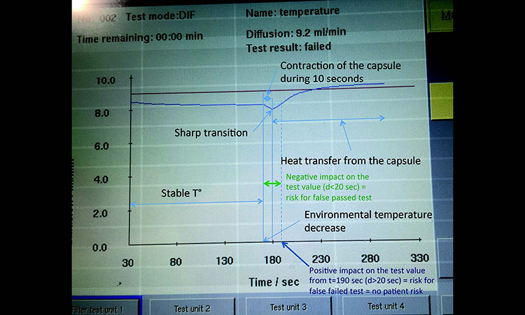
A diffusion test under stable environmental conditions at an ambient temperature of 22°C was performed on a 5-inch PP capsule (with half the wall thickness of the 10-inch capsule). After 175 seconds of measurement the filter capsule was entirely submerged into a bucket with water at 17°C to generate a quick temperature decrease. The diffusion curve is shown in Figure 4.
Interpretation
The general shape of the diffusion curve is, as expected, identical to the previous trial with the 10-inch capsule.
Differences can be seen in the contraction phase, which is shorter, and the transition from contraction to heat transfer phase, which also goes faster, thus creating a sharp “knee” rather than a slow transition. The PP wall of the 5-inch capsule is indeed thinner than for the 10-inch capsule; outer wall surface-to-gas volume ratio is greater for the 5-inch capsule. Heat transfer from the test gas to the water is therefore faster for the 5-inch capsule; the more accentuated slope of the curve indicates this.
When the heat transfer takes place from the test gas to the water, the pressure drop per time increases. This is interpreted by the integrity tester as an increase of the diffusion rate and, in this particular case, a false failed test result.
| Material | Linear coefficient α at 20°C (10–6 K–1) | Volumetric coefficient ΑV at 20°C (10–6 K–1) |
|---|---|---|
| Aluminum | 23.1 | 69 |
| Platinum | 9 | 27 |
| PP | 150 | 450 |
| PVC | 52 | 156 |
| Sitall* | 0 ± 0.15 | 0 ± 0.45 |
| Stainless steel | 10.1 ~ 17.3 | 51.9 |
| Steel † | 11.0 ~ 13.0 | 33.0 ~ 39.0 |
|
* Average for –60°C to 60°C † Depends on composition |
||
Test 5
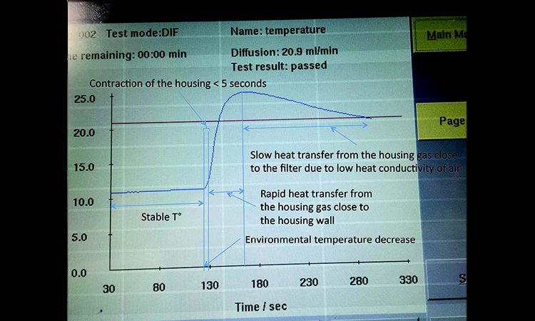
A diffusion test under stable environmental conditions at an ambient room temperature of 22°C was performed on a 10-inch filter cartridge in a stainless steel housing. After 125 seconds of measurement, the filter capsule was entirely submerged into a bucket with water at 17°C to generate a quick temperature decrease (Figure 5).
Interpretation
The stainless steel housing contracts when it enters the cold water and its volume is reduced, but to a much smaller extent than the PP capsule because the thermal expansion coefficient of stainless steel is 9 times smaller than PP (Table A). In contrast to the PP capsule, therefore, the stainless steel housing does not generate any initial reduction of the measured diffusion when being cooled. The curve shows just a very short phase of slow diffusion increase as the temperature decrease of the test gas has a much greater impact than the volume reduction.
Because heat transfer is much faster for stainless steel than for PP, the air inside the housing close to the wall cools rapidly. The effect on the measured pressure drop per time gives a steep slope to the diffusion curve. When the air close to the wall has cooled, heat transfer is slower and pressure drop per time also slows. The integrity tester interprets this as reduction of the average diffusion rate.
Figures 6 and 7 summarize the behavior of these two samples. No diffusion graphs from putting stainless steel housing into hot water are available because the integrity tester interrupts the test as soon as it detects the pressure increase.
Test 6
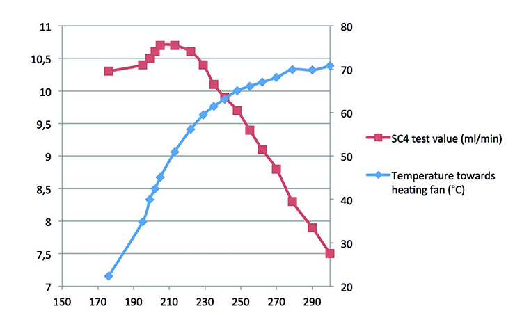
A diffusion test under stable environmental conditions at an ambient temperature of 22°C was performed on a 10-inch filter capsule with a temperature sensor attached to the wall. After 176 seconds of measurement, one side of the capsule was exposed to a heating fan that generated a progressive temperature increase from 22°C to 71°C (Figure 8). Relative air humidity was between 40% and 60%. The difference between this trial and those that put the filter capsule in warm water is that the heat only comes from one side and is progressive. The humidity was also much lower, which influenced the heat transfer, and the temperature was higher, going up to 71°C.
Interpretation
With a continuous temperature increase from t = 176 seconds, there is a mix of volume increase and heat transfer until the end of the test, after the 15 seconds it takes for the heat to get through the PP wall of the filter capsule. This, combined with the poor conductivity of air inside the capsule, resulted in a much lower impact on the test result than was expected from the ideal gas law.
Diffusion Test
The ideal gas law pV = nRT can be derived to:
p1 × V1 ÷ T1 = p2 × V2 ÷T2
Where
p1 = Pressure before the temperature change (e.g., 3,500 mbar absolute)
p2 = Pressure after the temperature change
T1 = Temperature of the test gas before the temperature change (e.g., 273 K)
T2 = Temperature of the test gas after the temperature change (e.g., 272 K)
V1 and V2 = Net sample volume, considered as constant for stainless steel housings
Therefore
p1 ÷ T1 = p2 ÷T2
and
p1 × T2 ÷ T1 = p2
Numerical application
3500 mbar × 272 K ÷ 273 K ≈ 3487 mbar
3487 mbar – 3500 mbar = –13 mbar
A typical pressure drop during the 5-minute diffusion test time is 50 mbar. The impact is then calculated as:
–13 ÷ 50 × 100% = –26%
The 26% pressure reduction from the temperature change results in a measured diffusion increase of 26%.
Diffusion vs. Bubble-Point Test
A diffusion test measures the drop from the specified test pressure in a known volume over a period of time. The pressure drop takes place because the test gas dissolves into the membrane wetting liquid and passes through the membrane without expelling the wetting liquid. The pressure drop is converted into diffusion, per DIN 58356 part 2:
\( \text{Diffusion} = \frac{p_1xV_{net}}{t x p_{net}}x In \frac{p_1}{p_1 - \Delta p}[ml/min] \)
If there is an environmental temperature variation during the measurement phase beyond recommended limits (±1°C per 5 minutes), 5 minutes can be enough to allow a certain heat transfer to take place. Very short measurements would be less affected, due to thermal inertia, but could yield too-low pressure drops and not provide the required accuracy.
Bubble-point detection measures pressure drop in a known volume at higher and higher pressures. After each pressure increase there is a stabilization phase of about 6 seconds that compensates for an eventual thermal impact. Each pressure drop is converted into a flow value. The bubble-point detection then compares flow values at every pressure step. When an exponential increase takes place, it means that the wetting liquid has been expelled from the biggest pores. The differential pressure at which this takes place is the bubble-point value.
The bubble-point method consists of several short measurement steps with a short stabilization step in between, combined with a relative comparison between subsequent values. As a result, temperature variations are less important and could be demonstrated by a calculation similar to the diffusion. Should this be of interest, please contact the author.
HEAT TRANSFER
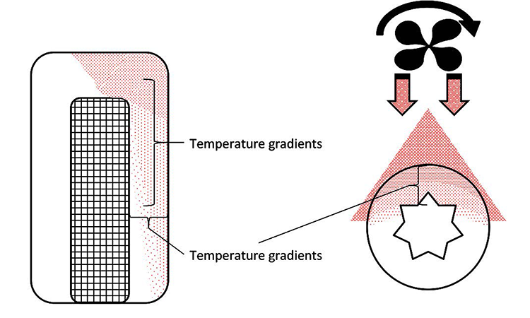
Because air is a poor conductor of heat, there will be obvious horizontal temperature gradients inside the sample being subjected to the temperature change. Additionally, because hot air has a lower density than cold air, hot air will rise inside the sample and create vertical temperature gradients.
If the temperature change comes from only one side, heat transfer will generate temperature gradients as shown in Figure 9. The volume change will also be affected, because the sample will expand in an uneven way.
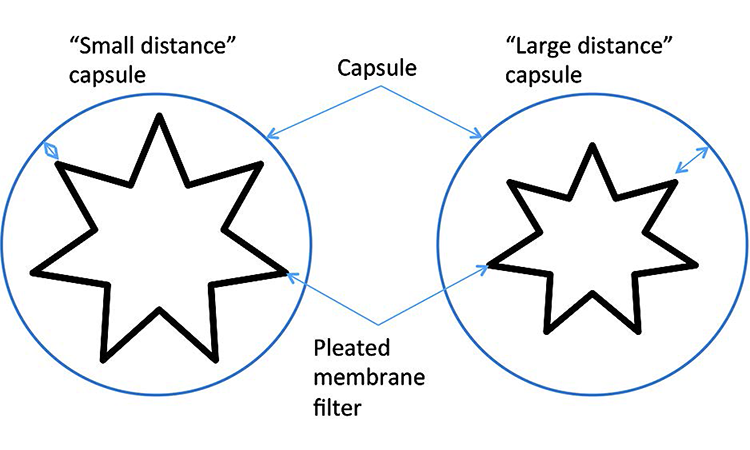
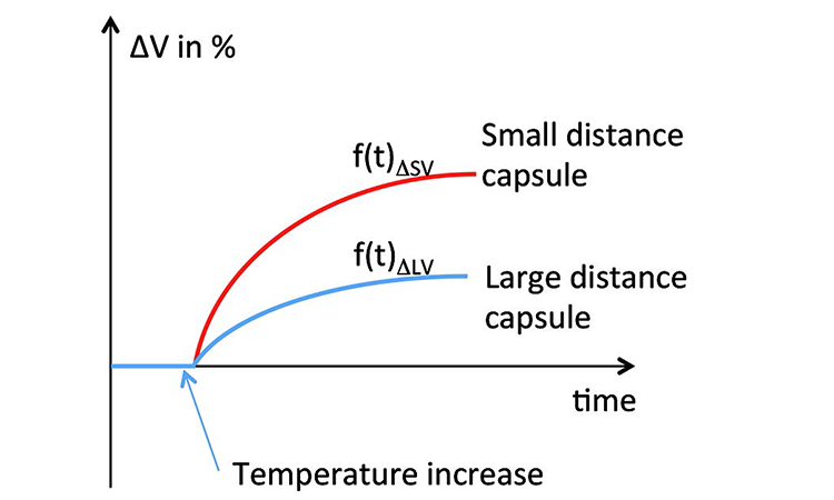
The effect on the test value due to expansion or retraction is dependent on the sample dimensions and net volume: Under identical environmental conditions a filter capsule with a small distance between the filter and the outer wall of the capsule will show a greater impact on the test value than a capsule of same dimensions with a large distance between the filter and the outer wall (Figure 10). The time-dependent function for volume change can be represented as f (t) ΔV (Figure 11). A sample encapsulated in a holder (e.g., single-use bag) between restraining plates further delays the heat transfer from the environment.
CONCLUSIONS AND DISCUSSION
Environmental temperature drifts may have an important effect on integrity test value and may generate false passed and false failed test results; the former can put patients’ lives in danger, while the latter can contribute to drug shortages. Stable temperature is therefore a prerequisite for reliable integrity testing. Even when stable temperature is part of the standard operating procedure, however, temperature drifts can still occur.
“Stable temperature is a prerequisite for reliable integrity testing”
A robust risk assessment of thermal impact (such as FMEA) on FIT and CCIT that quantifies the effects, defines preventive actions, and improves detectability will help mitigate the risk. It will also increase awareness for both operators and quality assurance.
The trials discussed in this article clearly indicate that a risk assessment based solely on the ideal gas law is not adequate. Saying that a temperature decrease of the environment is not quality-critical because it could only increase the diffusion value is wrong. Thermal expansion or contraction of polymer samples (e.g., single-use filter capsules and bags) will counterbalance the prediction of the ideal gas law. Temperature gradients inside the sample will also make predictions difficult regardless of sample material.
The thermal counterbalancing effects of polymer samples apply differently for different materials; in addition, heat-transfer delay between the environment and the test gas is directly affected by wall thickness. Not taking all these parameters into account will lead to false assumptions.
Working under stable thermal conditions, and monitoring and recording temperatures at the point of use help reduce the risk for false passed and false failed test results. Temperature data could be included in the batch report. Stable environmental conditions could be defined as:
- Environmental temperature changes below or equal to ±1°C per 5 minutes
- No draft (no direct HVAC airflow)
- No direct sunlight
- No nearby heat sources such as autoclaves, heat-jacketed bioreactors, or warm piping
The operator must also avoid touching or moving the tubing and/or the sample being tested. Filter wetting should only be done with a liquid at ambient temperature ±1°C, unless validated.Knowing the specific behavior of the sample when exposed to monitored temperature changes would make it possible to use software algorithms in the integrity testing device to either predict its impact on the test result or adjust the measured value to eliminate the risk for false passed and false failed results.
References
- Parenteral Drug Association. “Sterilizing Filtration of Liquids.” Technical Report No. 26 (Revised 2008). Supplement to PDA Journal of Pharmaceutical Science and Technology 62, no. S-5 (2008).
- International Conference on Harmonisation of Technical Requirements for Registration of Pharmaceuticals for Human Use. “Quality Risk Management: Q9.” 9 November 2005. http://www.ich.org/fileadmin/Public_Web_Site/ICH_Products/Guidelines/Quality/Q9/Step4/Q9_Guideline.pdf
- Functional design specifications of the integrity tester device
- The Engineering Toolbox. “Coefficients of Linear Thermal Expansion.” http://www.engineeringtoolbox.com/linear-expansion-coefficients-d_95.html
- Deutsches Institut für Normung eV. Standard DIN 58356-2: “Membrane filter elements, Part 2: Pressure Holder Tests.” 8 January 2000


